Exploring the Amiga - Part 5
By Leonardo Giordani - Updated on
Memory management is always one of the most rich and complex parts of an architecture, mainly because the available amount of memory is always less than what you would like to have. Always.
It is also an interesting topic because memory is generally managed by both the hardware and the software. The microprocessor may provide a memory management unit (MMU) that enforces a specific schema and the software has to implement its own algorithms on top of that.
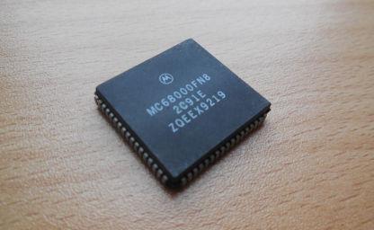
The Amiga originally run on a Motorola 68k, which doesn't provide any memory management in hardware. This means that there is no way for the processor to block attempts to read memory by a process, a feature that wasn't present on the first Intel x86 processors as well. Intel "solved" the issue with the introduction of the protected mode in the 386 family (even though an initial version was already present on the 286 processors). Motorola provided external MMUs for the 68010 and 68020, while the 68030 and later processor feature an on-chip MMU.
The Motorola 68k is a 32-bit processor, thus registers and the address bus have that size. The memory, however, is connected to only 24 of the 32 lines of the bus, which means that the total memory space addressable by the processor is a 24-bit space, that gives 16 Megabytes instead of the possible 4 Gigabytes. That amount of memory was however enough for the period when the Amiga was designed. Consider that the most successful model of Amiga, the Amiga 500, had 500 KBytes of memory, sometimes increased to 1 Megabyte through a memory expansion.
The lack of a memory scheme enforced by the processor means that at boot time the memory is just a flat area that can be addressed directly. As we saw in the previous instalments, Exec creates its own structure in memory, generating the library node and creating the library jump table. This happens in the bigger picture of the machine initialisation, and one of the tasks performed during this initialisation is the setup of the memory management structures.
The Exec base address
Every Amiga programmer knows that address 0x4 contains the Exec base address, and I showed in past instalments how this is used in conjunction with the jump table to call the library functions.
The reason why the Exec base address is stored there is however seldom mentioned. As a matter of fact that address is not just a random choice.
The Motorola 68000 family reserves the first Kilobyte of memory for exception vectors, that is code that will be executed when something wrong happens. "Wrong" here means bad at hardware level, from a divide by zero to a bus error. This is enforced by the Motorola 68k architecture and thus is a feature shared by other computers and consoles based on it.
The first two of these vectors are actually used when the processor is powering-up (or in general when it resets). And the vector number 1 (the second) at offset 0x4 is the Reset Initial Program Counter.
After a reset the processor initialises the Program Counter with the address stored at 0x4 in the memory. When the CPU is switched on, however, the Kickstart ROM is copied in memory, thus the addresses 0 and 4 (first two exception vectors) are the addresses listed in the ROM itself.
The very first 8 bytes of the Kickstart ROM are
00000000: 1111
00000002: 4ef9 00fc 00d2            jmp     0xfc00d2.l
and you can clearly see that the long word at address 0x4 is 00fc 00d2. This actually corresponds to the address where the initial code of the ROM is
000000d2: 4ff9 0004 0000 lea 0x40000.l,sp
which sets the stack pointer, but I'll keep this analysis for a future post.
The address 0x4 is then free to be used during the normal execution, since it is used only during a reset, but in that case whatever we wrote there (the Exec base address) is overwritten by the ROM code.
List headers
Exec manages memory and resources using linked lists. As you know, to manage a linked list we need the address (pointer) of the head, of the tail, and also of the second-to-last element (the tail predecessor), to allow the tail to be detached and replaced. Actually it is evident that, given the convention that the last node is connected to the address 0, the only value we need is the address of the list head. The two additional addresses, however, can greatly simplify the code that manages the list and can greatly increase the performances, avoiding the need of a complete scan of the list to find the last element every time we want to add something to the end of the list.
The Exec library provides a nice structure to manage lists, LH. The structure is defined in include_i/exec/lists.i
   STRUCTURE    LH,0
    APTR    LH_HEAD
    APTR    LH_TAIL
    APTR    LH_TAILPRED
    UBYTE   LH_TYPE
    UBYTE   LH_pad
    LABEL   LH_SIZE ;word aligned
The only two fields that this structure adds compared to the previous description are LH_TYPE, that unsurprisingly contains the type of the data contained in the list, and LH_pad which is nothing but what the name suggests, a padding that allows the structure to be word aligned.
We need now to discover where Exec keeps the header for the memory list. Analysing the ExecBase structure contained in include_i/exec/execbase.i we find the following definitions
******* System List Headers (private!) ********************************

    STRUCT  MemList,LH_SIZE
    STRUCT  ResourceList,LH_SIZE
    STRUCT  DeviceList,LH_SIZE
    STRUCT  IntrList,LH_SIZE
    STRUCT  LibList,LH_SIZE
    STRUCT  PortList,LH_SIZE
    STRUCT  TaskReady,LH_SIZE
    STRUCT  TaskWait,LH_SIZE
    STRUCT  SoftInts,SH_SIZE*5
which is exactly what we wanted. When Exec installs itself in the first part of the memory it will also initialise these headers to keep track of the corresponding resources.
It is interesting to note, however, that the ExecBase structure described in the include files is not used directly, but is more a description of what the code is going to create. This is a bit different from what higher level languages like C use to do. In C you declare a structure, you reserve memory for it, and then access its fields. In Assembly, ultimately, there is no such a concept as a structure and a field. We have only a (flat) memory and addresses.
Since ExecBase is a description of the structure of Exec once it will be installed in memory it is interesting to run through its fields and annotate the relative address of each of them.
I took the code contained in include_i/exec/execbase.i and I computed the address of each field. The first column contains the relative address inside the structure (thus starting from 0x0), while the second column contains the address relative to the Exec base address. As shown in the fourth post the LN and LIB structures fill the first 34 bytes, which is why the following starting address is 0x22
0000 0022    UWORD   SoftVer ; kickstart release number (obs.)
0002 0024    WORD    LowMemChkSum    ; checksum of 68000 trap vectors
0004 0026    ULONG   ChkBase ; system base pointer complement
0008 002a    APTR    ColdCapture ; coldstart soft capture vector
000c 002e    APTR    CoolCapture ; coolstart soft capture vector
0010 0032    APTR    WarmCapture ; warmstart soft capture vector
0014 0036    APTR    SysStkUpper ; system stack base   (upper bound)
0018 003a    APTR    SysStkLower ; top of system stack (lower bound)
001c 003e    ULONG   MaxLocMem   ; top of chip memory
0020 0042    APTR    DebugEntry  ; global debugger entry point
0024 0046    APTR    DebugData   ; global debugger data segment
0028 004a    APTR    AlertData   ; alert data segment
002c 004e    APTR    MaxExtMem   ; top of extended mem, or null if none

0030 0052    WORD    ChkSum      ; for all of the above (minus 2)


******* Interrupt Related ********************************************

    LABEL   IntVects
0032 0054    STRUCT  IVTBE,IV_SIZE
003e 0060    STRUCT  IVDSKBLK,IV_SIZE
004a 006c    STRUCT  IVSOFTINT,IV_SIZE
0056 0078    STRUCT  IVPORTS,IV_SIZE
0062 0084    STRUCT  IVCOPER,IV_SIZE
006e 0090    STRUCT  IVVERTB,IV_SIZE
007a 009c    STRUCT  IVBLIT,IV_SIZE
0086 00a8    STRUCT  IVAUD0,IV_SIZE
0092 00b4    STRUCT  IVAUD1,IV_SIZE
009e 00c0    STRUCT  IVAUD2,IV_SIZE
00aa 00cc    STRUCT  IVAUD3,IV_SIZE
00b6 00d8    STRUCT  IVRBF,IV_SIZE
00c2 00e4    STRUCT  IVDSKSYNC,IV_SIZE
00ce 00f0    STRUCT  IVEXTER,IV_SIZE
00da 00fc    STRUCT  IVINTEN,IV_SIZE
00e6 0108    STRUCT  IVNMI,IV_SIZE


******* Dynamic System Variables *************************************

00f2 0114    APTR    ThisTask    ; pointer to current task (readable)

00f6 0118    ULONG   IdleCount   ; idle counter
00fa 011c    ULONG   DispCount   ; dispatch counter
00fe 0120    UWORD   Quantum ; time slice quantum
0100 0122    UWORD   Elapsed ; current quantum ticks
0102 0124    UWORD   SysFlags    ; misc internal system flags
0104 0126    BYTE    IDNestCnt   ; interrupt disable nesting count
0105 0127    BYTE    TDNestCnt   ; task disable nesting count

0106 0128    UWORD   AttnFlags   ; special attention flags (readable)

0108 012a    UWORD   AttnResched ; rescheduling attention
010a 012c    APTR    ResModules  ; pointer to resident module array
010e 0130    APTR    TaskTrapCode    ; default task trap routine
0112 0134    APTR    TaskExceptCode  ; default task exception code
0116 0138    APTR    TaskExitCode    ; default task exit code
011a 013c    ULONG   TaskSigAlloc    ; preallocated signal mask
011e 0140    UWORD   TaskTrapAlloc   ; preallocated trap mask


******* System List Headers (private!) ********************************

0120 0142    STRUCT  MemList,LH_SIZE
012e 0150    STRUCT  ResourceList,LH_SIZE
013c 015e    STRUCT  DeviceList,LH_SIZE
014a 016c    STRUCT  IntrList,LH_SIZE
0158 017a    STRUCT  LibList,LH_SIZE
0166 0188    STRUCT  PortList,LH_SIZE
0174 0196    STRUCT  TaskReady,LH_SIZE
0182 01a4    STRUCT  TaskWait,LH_SIZE
0190 01b2    STRUCT  SoftInts,SH_SIZE*5

01e0 0202    STRUCT  LastAlert,4*4

01f0 0212    UBYTE   VBlankFrequency     ;(readable)
01f1 0213    UBYTE   PowerSupplyFrequency    ;(readable)

01f2 0214    STRUCT  SemaphoreList,LH_SIZE

0200 0222    APTR    KickMemPtr  ; ptr to queue of mem lists
0204 0226    APTR    KickTagPtr  ; ptr to rom tag queue
0208 022a    APTR    KickCheckSum    ; checksum for mem and tags

020c 022e    UBYTE ExecBaseReserved[10];
0216 0238    UBYTE ExecBaseNewReserved[20];
022a 024c    LABEL   SYSBASESIZE
According to this structure we expect to find the memory list header 322 bytes (0x142) after the base address, which means that this number should be mentioned somewhere in the Kickstart code.
It is not surprise indeed that the function AllocMem mentions it. This function is part of the Exec API that we explored in the third and fourth instalments. Following the same method described there I found the function at the address 0x17d0 in the Kickstart code
; memoryBlock = AllocMem(byteSize, attributes)
; d0                     d0        d1

000017d0: 522e 0127                 addq.b  #0x1,0x127(a6)
000017d4: 48e7 3020                 movem.l d2-d3/a2,-(sp)
000017d8: 2600                      move.l  d0,d3
000017da: 2401                      move.l  d1,d2
000017dc: 45ee 0142                 lea     0x142(a6),a2
000017e0: 2452                      movea.l (a2),a2
; ...
and in this initial part of the function we can clearly see the code that loads the effective address of 0x142(a6). Remember that a6 is always supposed to contain the Exec base address.
The displacement 0x142 is also mentioned in a table towards the beginning of the code, and this is the part we are really interested in at the moment
; Initialise list headers

000002b0: 43fa 0020                 lea     0x2d2(pc),a1
000002b4: 3019                      move.w  (a1)+,d0
000002b6: 6700 0086                 beq.w   0x33e
000002ba: 41f6 0000                 lea     (0,a6,d0.w),a0
000002be: 2088                      move.l  a0,(a0)
000002c0: 5890                      addq.l  #0x4,(a0)
000002c2: 42a8 0004                 clr.l   0x4(a0)
000002c6: 2148 0008                 move.l  a0,0x8(a0)
000002ca: 3019                      move.w  (a1)+,d0
000002cc: 1140 000c                 move.b  d0,0xc(a0)
000002d0: 60e2                      bra.b   0x2b4

; List headers

000002d2: 0142 000a
000002d6: 0150 0008
000002da: 015e 0003
000002de: 017a 0009
000002e2: 0188 0004
000002e6: 0196 0001
000002ea: 01a4 0001
000002ee: 016c 0002
000002f2: 01b2 000b
000002f6: 01c2 000b
000002fa: 01d2 000b
000002fe: 01e2 000b
00000302: 01f2 000b
00000306: 0214 000f
0000030a: 0000
As you can see I formatted the code to show that the values after 02d2 are data and not code. The disassembler will obviously show you some instructions but they are just misinterpretations of the binary data. AS it is usual in the Kickstart code, we have some procedure working on a set of data and the data is stored immediately after the code itself. The purpose of this procedure is that of creating the initial headers for the linked lists that Exec will use to manage the system resources.
This table is immediately followed by the table we found in the third post of this series, when we were looking at the values of the LIB structure.
Let's comment line by line the code at 02b0
; Initialise list headers

000002b0: 43fa 0020                 lea     0x2d2(pc),a1
000002b4: 3019                      move.w  (a1)+,d0
000002b6: 6700 0086                 beq.w   0x33e
000002ba: 41f6 0000                 lea     (0,a6,d0.w),a0
000002be: 2088                      move.l  a0,(a0)
000002c0: 5890                      addq.l  #0x4,(a0)
000002c2: 42a8 0004                 clr.l   0x4(a0)
000002c6: 2148 0008                 move.l  a0,0x8(a0)
000002ca: 3019                      move.w  (a1)+,d0
000002cc: 1140 000c                 move.b  d0,0xc(a0)
000002d0: 60e2                      bra.b   0x2b4
000002b0: 43fa 0020 lea 0x2d2(pc),a1
First of all the code loads the absolute address of 0x2d2(pc) in the a1 register. This is exactly the beginning of the table, as shown above.
000002b4: 3019                      move.w  (a1)+,d0
000002b6: 6700 0086                 beq.w   0x33e
The code then loads the first value of the table (0142) in d0 and increments a1. This suggests that we are looking at a loop. The following instruction is indeed a comparison that jumps to 0x33e is the value is 0. You can easily see above that the table is terminated by a 0000.
000002ba: 41f6 0000 lea (0,a6,d0.w),a0
The register a0 is then loaded with the effective address of Exec + d0. This means that we use the value we just read from the table as a pointer. For the first value, then, we are looking at 0x142 bytes after the beginning of the Exec library, exactly where we expected to find the Memory List header.
000002be: 2088                      move.l  a0,(a0)
000002c0: 5890                      addq.l  #0x4,(a0)
An empty linked list has the head pointing to the tail and the tail pointing to zero. To do this we set the content of that address (a0) to the address itself (a0), then we increment it by 4 making it point to the tail.
000002c2: 42a8 0004                 clr.l   0x4(a0)
000002c6: 2148 0008                 move.l  a0,0x8(a0)
The tail itself is then cleared and the tail predecessor is set to be the head.
000002ca: 3019                      move.w  (a1)+,d0
000002cc: 1140 000c                 move.b  d0,0xc(a0)
The code then fetches the next word from the table (000a) and puts it into a field 12 bytes (0xc) from the beginning of the structure, that is LH_TYPE. The possible values of this byte can be found in include_i/exec/nodes.i, where we find that the value 0xa corresponds to NT_MEMORY.
;------ Node Types for LN_TYPE

NT_UNKNOWN      EQU 0
NT_TASK         EQU 1   ; Exec task
NT_INTERRUPT    EQU 2
NT_DEVICE       EQU 3
NT_MSGPORT      EQU 4
NT_MESSAGE      EQU 5   ; Indicates message currently pending
NT_FREEMSG      EQU 6
NT_REPLYMSG     EQU 7   ; Message has been replied
NT_RESOURCE     EQU 8
NT_LIBRARY      EQU 9
NT_MEMORY       EQU 10
NT_SOFTINT      EQU 11  ; Internal flag used by SoftInts
NT_FONT         EQU 12
NT_PROCESS      EQU 13  ; AmigaDOS Process
NT_SEMAPHORE    EQU 14
NT_SIGNALSEM    EQU 15  ; signal semaphores
NT_BOOTNODE     EQU 16
NT_KICKMEM      EQU 17
NT_GRAPHICS     EQU 18
NT_DEATHMESSAGE EQU 19

NT_USER         EQU 254 ; User node types work down from here
NT_EXTENDED     EQU 255
There is only one instruction left
000002d0: 60e2 bra.b 0x2b4
which jumps back to the beginning of this short piece of code. The procedure then keeps looping on the whole table until it reaches the list terminator 0000.
The final content of the memory at 0142 will be
00000142: 0000 0146 ; LH_HEAD
00000146: 0000 0000 ; LH_TAIL
0000014a: 0000 0146 ; LH_TAILPRED
0000014d: 0a        ; LH_TYPE
And the same happens for the remaining 7 lists from ResourceList to TaskWait. After this the Exec lists are initialised.
According to the values of LN_TYPE the list headers table is the following
000002d2: 0142 000a ; MemList (NT_MEMORY)
000002d6: 0150 0008 ; ResourceList (NT_RESOURCE)
000002da: 015e 0003 ; DeviceList (NT_DEVICE)
000002de: 017a 0009 ; LibList (NT_LIBRARY)
000002e2: 0188 0004 ; PortList (NT_MSGPORT)
000002e6: 0196 0001 ; TaskReady (NT_TASK)
000002ea: 01a4 0001 ; TaskWait (NT_TASK)
000002ee: 016c 0002 ; IntrList (NT_INTERRUPT)
000002f2: 01b2 000b ; SoftInts[0] (NT_SOFTINT)
000002f6: 01c2 000b ; SoftInts[1] (NT_SOFTINT)
000002fa: 01d2 000b ; SoftInts[2] (NT_SOFTINT)
000002fe: 01e2 000b ; SoftInts[3] (NT_SOFTINT)
00000302: 01f2 000b ; SoftInts[4] (NT_SOFTINT)
00000306: 0214 000f ; SemaphoreList (NT_SIGNALSEM)
0000030a: 0000
What's next
The next instalment of the series will cover the initial part of the system memory initialisation, both the standard one and potential expansions, introducing AddMemList for the first time. It will also discuss the origin of some important numbers used in the Kickstart code, 0x24c, 0x400, and 0x676.
Resources
- Microprocessor-based system design by Ricardo Gutierrez-Osuna (slides), in particular Lesson 9 - Exception processing
- Motorola M68000 Family Programmer's Reference Manual - https://www.nxp.com/docs/en/reference-manual/M68000PRM.pdf
Feedback
Feel free to reach me on Twitter if you have questions. The GitHub issues page is the best place to submit corrections.
Part 5 of the Exploring the Amiga series
Related Posts

Exploring the Amiga - Part 8
Updated on

Exploring the Amiga - Part 7
Updated on

Exploring the Amiga - Part 6
Updated on

Exploring the Amiga - Part 4
Updated on

Exploring the Amiga - Part 3
Updated on

Exploring the Amiga - Part 2
Updated on

Exploring the Amiga - Part 1
Updated on

